I started off doing what seems to be the tail using arc
and line in the shapes tab. The idea was
simple enough, to draw it in 2D first and hopefully using the extrude to turn
it into a 3D object. As you can see I
had to make some adjustments as the image shows the tail starts off wide and
then narrows down.
I then adjusted the middle part and as you can see from
the picture above that I’m planning on modifying the polygon in order to make
it narrower. I then realised that polygons
is not the way forward. So i found
alternative ways to make it narrow at the bottom. In the picture below the tail was made narrow
by using a line tool, although not perfect and the corners are not attached, I’m
reasonably happy with it providing I can turn it into 3D.
After checking with my tutor I realised that there are a
few things wrong with what I was doing.
The main thing that was wrong about my approach is that I had to draw a
closed shape and not individual objects.
I also changed the glider that I wanted to model as the picture below
would suggest. This was due to the fact
that da Vinci designed at least two different types of glider and the Google search
engine didn’t differentiate between the types.
I created this by first drawing a box with the following
parameters:
Then converted it to editable poly, selected the vertex
mode and selected all 4 polygons at the two corners by holding ctrl and drag. The picture below is an example of what I
did.
I then dragged the Y axis in order to get the desired
effect. In order to evenly move the
edges in at the opposite end, I did the same thing but this time I used the
uniform tool like so:
In order to make it ‘flappy’ I was on the edge mode,
selected the line going through the centre (length segment) and clicked on loop
so that it would select the other 3 edges and then dragged the Z like so:
My progress so far.
All I did was add basic objects such as:
I duplicated, changed the parameters like sides etc.
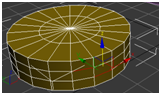
In order to model the pulley that is attach to the rope and
links the feet movement to the links, I had to draw a cylinder with two its
height segments set to 3. I then went to
the edge mode and I selected two edges like so:
I then loop them and dragged the whole thing inward
like so:
Then I had to delete the centre in order to make it go
into pole. I did this via the polygon
mode which took a little more time that I’d hoped for so asked the tutor if
there was a quicker way. The picture
below shows my progress.
The quicker way is to hold down the selection region and
select the appropriate one, which in this case is the circle, like so:
I then dragged and delete like so:
The alternative way of doing this is to do it with a tube
instead of the cylinder and it would have saved me a lot of times as all I had
to do was pull in the height segments.
The lecturer advised me to look back on the mapping
technique or the spline technique, in order to model the wings. The picture below is the finish article of
the mapping technique. Although I do see
the technique being incredibly useful in the future I fail to see how it could
help me model the wings, especially given the fact that the wings I am trying
to model are not angled appropriately.
So I explored the possibility of the spline technique.
As you can see from the picture above, I am having
extreme difficulty using the spline technique and especially the line tool, despite
the trial and error approach as well as markings.
I began to explore other ways of modelling the wings.
The picture above was my solution, or part of it. I decided to draw a box and use cut to add
polygons in accordance to the wing when looking at it in 2D. This technique enabled me to be both accurate
and quick. All I have to do now is
select and delete the corners of the box like so:
This turned out to be a bit of a mess. I thought that I could apply turbo smooth to
smooth the edges but this is what it did:
This could be because its essentially a flat shape. As you can see I had another go at it, but
this time I tried to move the vertexes into the correct position. With very little time i had to make a
decision to apply the flat as my wings:
After reviewing the wings, i felt there is still some
improvements to be made such as the ‘bone’:
The glider I was modelling resembled the bat, due to da
Vinci’s knowledge in anatomy, it would make sense that he used this knowledge,
in conjunction with his passion for flying, to come up with the design, as the
structure are very similar.
In order to attach the ‘bones’ or what looks like thin
treated woods, I had draw a thin cylinder and placing the polygons onto the
wings like so:
I then run out of polygons to place as the picture below
shows:
My solution was to either start again and make the
cylinder taller, or more simply add or ‘cut’ polygons
The problem with the second option is that I had to cut
all around the cylinder and not on one side otherwise it would look like the
picture below when I tried to place it:
I realised that would take twice as long so i started
again but this time i placed the end points first and worked around that:
I am not exactly
happy about this out come as the cylinder has been twisted and been made to
look thicker.
My 3rd and final attempt is to start again
with a cylinder that had significantly higher height segments which would give
me enough polygons when I convert it to editable poly. In all of these attempts the soft selection
was unchecked as I did not want it to affect other polygons.
This is my final design for my wings.
There could be improvements made to them for example I could fix
(smooth) the edges by adjusting the polygons just like I did for the bones/ treated
woods, but sadly I was out of time and needed to move on. Also I realised that the colour is different,
due to the one on the left (black) is showing its back as I rotated it.
My finished article below.
I finished it off using tubes, cylinders and changing
their parameters etc them to suit my needs and placing them in accordance to Leonardo
da Vinci’s drawings.


